CHALLENGE:
A customer requested a review for a 20 KW Electrical vehicle battery charger and system. Upon review, DRF discovered that the system had many fundamental flaws; for example, the gate drivers circuit did not have sufficient drive power to turn on the semiconductor devices. For the PCB layout, DRF uncovered issues related to proper gate signal layout.
DRF’S SOLUTION:
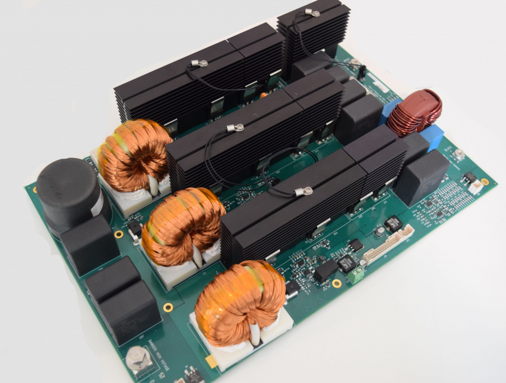
After peer review, the customer asked DRF to design a new converter board to replace the one they designed. DRF designed and developed a three-phase interleaved boost converter, which consisted of three boost converters, connected in a parallel layout, and operating at 120 degrees between phases. The current for this project was the sum of the three input inductors’ currents that were phase-shifted, and consequently, canceled each other out, thus reducing the ripple of the current and the amount of stress across each of the input capacitors. The advantages of using such interleaved topology are as follows:
- Switches connected in a parallel layout increase their overall reliability.
- 120 degrees set between phases increases the effectiveness of the switches’ frequencies and reduces the magnetic components’ total size and weight.
Key Features:
- Designed to meet CHAdeMO standards
- Topology: three-phase interleaved DC/DC boost
- Output power: 20 KW
- Input voltage: 75 to 150 VDC
- Output voltage: max of 500 V
- Silicon-Carbide (SiC) switching technology
- 99.2% efficiency at full load
- Constant output voltage or constant output current control
- Input and output voltages and currents, with real-time monitoring
- Pre-charge included

