Understanding and Measuring PWM Losses in High-Speed PM Motors: A Critical Step Toward Reliability

By Saad Thabit, Principal Engineer – DRF Engineering Services LLC

Measuring PWM Losses in High-Speed PM Motors

After spending more than a decade working with high-speed flywheel energy storage systems featuring motors spinning at 20,000 RPM in ultra-high vacuum environments (10⁻⁴ Torr)—I’ve developed a keen appreciation for the significance of every single watt of power loss. In such extreme operating conditions, even minor inefficiencies can lead to a measurable temperature rise, reduced efficiency, and, ultimately, system failure.

Among the most prevalent failure mechanisms in Permanent Magnet (PM) motors is rotor overheating, particularly at the shaft. This is often a direct consequence of high-frequency power losses, primarily introduced by Pulse Width Modulation (PWM) switching in modern motor drive systems.

Why Motor PWM Losses Are a Critical Concern

PWM switching techniques are widely used in inverters and motor drives to precisely control torque and speed. However, these high-speed switching operations introduce voltage and current harmonics, which in turn induce eddy currents and localized heating in the motor—especially in the rotor. This is a critical issue in high-speed applications, where the rotor lacks efficient cooling paths and thermal mass.

The accumulation of heat in the rotor over time can cause:

  • Demagnetization of permanent magnets
  • Degradation of insulation and bearings
  • Premature motor failure

Therefore, accurately quantifying PWM-induced losses is essential for ensuring motor reliability, validating thermal models, and optimizing drive system performance.

Measuring PWM Losses: Methodology

To accurately assess and Measure PWM Losses in a PM motor system, you must measure the total electrical power delivered to the motor and isolate the losses caused by high-frequency harmonics.

  1. Instrumentation Setup: Install a high-accuracy power analyzer between the drive and the motor.
  2. Data Acquisition: Use high-bandwidth voltage and current sensors to simultaneously capture all three-phase signals at high sampling rates.
  3. Power Analysis: Calculate PWM losses using the formula:

The general approach involves the following steps:

PLoss_PWM=P_RMS−P_Fundamental

Where:

  • P_RMSP is the total root mean square power, inclusive of harmonic components
  • P_ Fundamental is the power at the system’s fundamental frequency only

This approach effectively isolates the high-frequency harmonic contribution that results from switching.

Recommended Test Equipment

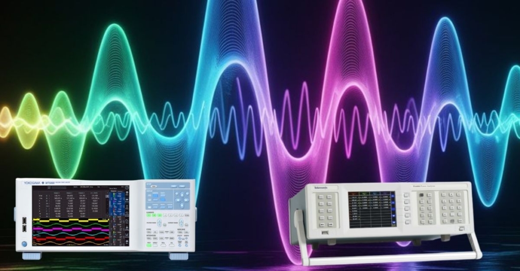
Based on our experience at DRF Engineering Services, the Tektronix PA4000 and Yokogawa WT5000 power analyzers are ideal for this application. These instruments provide high-resolution, high-accuracy measurements of both RMS and fundamental power components, even in systems with complex switching patterns and steep waveform edges.

Beyond Measurement: Simulation and Design Optimization

While measurement is essential, early-stage simulation is equally important for minimizing losses at the design phase. At DRF Engineering Services LLC, we provide simulation support to help engineers:

  • Model inverter/motor systems with high fidelity
  • Analyze harmonic impact and EMI behavior
  • Select optimal topologies and switching schemes
  • Predict thermal performance under worst-case conditions

Whether you’re working on a motor drive, DC/DC converter, or grid-tied inverter, our team can help you identify critical inefficiencies and propose robust, scalable solutions.


Get Expert Help With Your Power Electronics Design

At DRF Engineering Services, we bring over 30 years of practical expertise in power electronics, embedded controls, and product validation. From simulation to lab testing and pre-compliance review, we act as an extension of your engineering team to accelerate innovation and improve product quality.

Request a Consultation Today Visit www.drfengineeringservices.com to learn more.


Saad Thabit is the founder and principal consultant at DRF Engineering Services LLC, specializing in power conversion systems, embedded control, and compliance testing. With a proven track record across energy, industrial, and transportation sectors, Saad supports companies from concept through commercialization with deep technical insight and lab-proven results.

80AMPS All In One ESC for drones

DRF is pleased to announce the release of the prototype design of our high current Brushless Motor Drive. Capable of delivering a peak current of 80 Amps, it offers a wide operating voltage range of 30 to 100 Volts, and it can safely operate at temperatures up to 50°C. The unit is designed for use as an Electronic Speed Control (ESC) for drones, as well as for battery-powered tools; such as drills, grinders, and cutters. 

 DRF’s proprietary all-in-one board includes: 

  • A micro controller 
  • A power stage 
  • A gate driver 
  • Temperature monitoring for the switching MOSFETs 
  • Protection against voltage transients 
  • A Controller Area Network (CAN Bus) 
  • Onboard protection against under-voltage, over-current, and over-temperature 

 Handling 80 Amps on a Single-Board Device: 

Designing an 80 Amp peak current with SMD switching devices was very challenging; particularly, because of the size and weight of the heat sinks normally required for cooling the switching of the MOSFETs. To achieve this goal, each of the PCB’s eight layers included two ounces of copper to spread the heat away from the MOSFET junction. Then, we added more than 500 ten mil(0.254 mm) thermal micro vias, in order to reduce thermal resistance of the system. In this manner, we caused the removal of excess heat from the die, through the PCB, to the ambient environment. 

Great for UAV’s! 

The 80 Amp peak current, and the superior efficiency that our Brushless Motor Drive provides, makes it possible for UAVs to stay in the air longer, in order to endure harsh headwinds, and all the while carry larger payloads. 

Who We Are: 

We are an innovative design and development team, specializing in power electronic circuitry and power conversion products. We primarily provide product design/electrical engineering services and have worked with cutting edge companies like yours in the past.  

 Our services include: 

  • Analog/Digital/Power circuit design 
  • Linear/Switching regulator design 
  • Electro-mechanical product design and program management 
  • Power Management  
  • Manufacturing support 
  • Pre-compliance review and test support (certification and test management for IEC and UL)  
  • Due Diligence and Private Equity Advisory Services 
  • CAD design services, schematics capture, and board layout 

To learn more about our services, customers feedback, and product success stories please visit us at: http://www.drfengineeringservices.com 

Design Guide To Creating Your Next Inductor

Welcome to the December edition of DRF’s newsletter! This month, Saad Thabit presents a guide for designing a custom inductor,using C Cut-Cores. 

Do you have a new inductor design in mind, but don’t know what to use? 

Look no further! Amorphous metal and nanocrystalline are the best available options for your designs requiring the highest efficiency, and here’s why: 

  • High permeability leads to increased inductance and reduces winding turns, resulting in reduced I2R losses. 
  • High saturation induction will reduce size of the inductor. 
  • High frequency will range from 50Hz up to 100KHz. 
  • High operating temperatures can reach up to 120℃. 
  • Low coercivity increases the efficiency, and reduces hysteresis loss.   
  • Low core loss reduces energy consumed, and minimizes the temperature rise.  

Filter inductor designs, the values of the inductance, inductor current, operating frequency, ripple current and power losses will be determined by the following application:  

V_ind = 2*π*f*L*I_Peak 

Where: 

  • f = Inductor operating fundamental frequency 
  • L = Inductance value 
  • I Peak = Inductor peak current 

How to calculate the cross-sectional area product Ap: 

 Ap = [V ind*I peak*10^4] / [Kf*Ku*B peak*f*J] 

Where:  

  • Ap units are in cm4 
  • Kf =4.44 for sine waveforms 
  • Ku is the core window utilization fill factor 
  • B peak is the flux density in Tesla 
  • f is the operating frequency in Hz 
  • J is the current density in Amp / cm2  

The Ap product of a C-type cut core is the product of the available window area (Wa) of the core in square centimeters (cm2), multiplied by the effective cross-sectional area (Ac) in square centimeters (cm2), which may be stated as: 

A p = W a x Ac [cm4] 

Figure 1 (shown above) shows the outline form of a C-core type inductor; typical of those shown in the catalogs of suppliers. 

From this, it can be seen that [Wa] is the BC product, and [Ac] is the AD product. 

The AC inductor must support the applied voltage V ind. The number of turns is calculated from Faraday’s Law, shown below: 

N = [V ind*10^4] / [L*Kf*B peak*f*Ac] [Turns] 

Now, we can calculate the air gap with the equation below: 

Lg = [0.4*π*N^2*Ac*10^-8]/ L 

Where: 

  • L is the inductance, measured in Henry 
  • AC is measured in cm2 
  • Lg is the gap in cm 

Keep in mind, the fringing flux will decrease the total reluctance of the magnetic path, therefore increasing the inductance, by a factor F; all of which can be found in the formula below: 

F = [1+(Lg/sqrtAc) *(Ln(2*C/Lg))]  

Now that our major inductor parameters have been identified, we need to determine the inductor wire size. 

 Calculate inductor bare wire area Awire: 
  Awire =   I peak/J [cm2]  

Select the wire from the wire manufacturer table. For reference, you can use the  table supplied in this link.    

Now, we have determined the wire size. If we also know the mean turn length, as well as the number of turns, then we can determine the total length of the wire. From there, we can calculate the DC winding resistance, using the formula: 

R dc = MLT*N*resistance per unit length [Ohm] 

Where: 

Resistance per unit length as read from the wire tables for the selected wire size. 

 The losses in an ac inductor are made up of three components: 

  1. Copper loss, Pcu
    2. Iron loss, Pfe
    3. Gap loss, Pg  
  • Copper Losses, Pcu 

Pcu = (IL)^2 *R dc [Watts] 

  • Iron losses, Pfe 

For amorphous metal, use the following equation: 

Watt/Kilogram = 6.5 * f(KHz)^1.51*Bac(T)^1.74 

For Nano-crystalline use the following equation: 

Watt/Kilogram=1.8 * f(KHz)^1.53*Bac(T)^1.52

Where:

Bac is the flux density, and can be calculated using the formula below: 

 Bac = [ L*di] / [2*N*A][Tesla]  

Variables: 

 L inductance in Henry 
 Ac core cross section area in m² 

  • Gap loss, Pg 

Pg = Ki* a*Lg*f*Bac^2 [watt]

Where:  

  • a is the core strip width in cm (see Figure 1 above) 
     
  • f is frequency in Hertz 
     
  • Lg is the gap width in cm 
     
  • Ki is the Gap loss Coefficient 

 To calculate total indicator losses, use the following equation: 

P total = Pcu + Pfe + Pg [Watts] 

From here, you can calculate the inductor temperature rise, after calculating the inductor surface area. 

As the resistivity of the copper winding increases with temperature, the winding loss increases with temperature as well. In the magnetic materials, the core loss increases with the increasing temperature, above approximately 100-degrees C. The value of the saturation flux density becomes smaller with increases in the temperature. 
Winding and core loss causes the temperature increase; therefore, the loss must be kept below some maximum value. In practice, the maximum temperature is usually limited to 100-125 degrees C by several considerations, which include the reliability of the insulation on the copper winding, and inductor insulation system. 

For Additional assistance in inductor designs, contact DRF Engineering Services with your custom inductor design request. 

Who We Are: 

We are an innovative design and development team, specializing in power electronic circuitry and power conversion products. We primarily provide product design/electrical engineering services, and have worked with cutting edge companies like yours in the past.  

Our services include, but are not limited to the following:  

  • Analog/Digital/Power circuit design 
  • Linear/Switching regulator design 
  • Electro-mechanical product design and program management 
  • Power Management  
  • Manufacturing support 
  • Pre-compliance review and test support (certification and test management for IEC and UL) 
  • Due Diligence and Private Equity Advisory Services 
  • CAD design services, schematics capture, and board layout