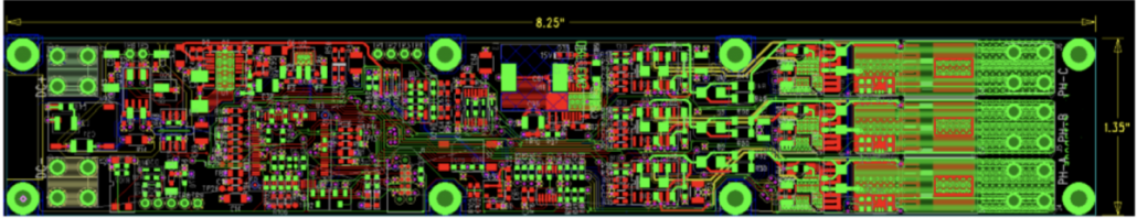
DRF is pleased to announce the release of the prototype design of our high current Brushless Motor Drive. Capable of delivering a peak current of 80 Amps, it offers a wide operating voltage range of 30 to 100 Volts, and it can safely operate at temperatures up to 50°C. The unit is designed for use as an Electronic Speed Control (ESC) for drones, as well as for battery-powered tools; such as drills, grinders, and cutters.
DRF’s proprietary all-in-one board includes:
A micro controller
A power stage
A gate driver
Temperature monitoring for the switching MOSFETs
Protection against voltage transients
A Controller Area Network (CAN Bus)
Onboard protection against under-voltage, over-current, and over-temperature
Handling 80 Amps on a Single-Board Device:
Designing an 80 Amp peak current with SMD switching devices was very challenging; particularly, because of the size and weight of the heat sinks normally required for cooling the switching of the MOSFETs. To achieve this goal, each of the PCB’s eight layers included two ounces of copper to spread the heat away from the MOSFET junction. Then, we added more than 500 ten mil(0.254 mm) thermal micro vias, in order to reduce thermal resistance of the system. In this manner, we caused the removal of excess heat from the die, through the PCB, to the ambient environment.
Great for UAV’s!
The 80 Amp peak current, and the superior efficiency that our Brushless Motor Drive provides, makes it possible for UAVs to stay in the air longer, in order to endure harsh headwinds, and all the while carry larger payloads.
Who We Are:
We are an innovative design and development team, specializing in power electronic circuitry and power conversion products. We primarily provide product design/electrical engineering services and have worked with cutting edge companies like yours in the past.
Our services include:
Analog/Digital/Power circuit design
Linear/Switching regulator design
Electro-mechanical product design and program management
Power Management
Manufacturing support
Pre-compliance review and test support (certification and test management for IEC and UL)
Due Diligence and Private Equity Advisory Services
CAD design services, schematics capture, and board layout
/wp-content/uploads/2021/09/logo-1.png00Saad/wp-content/uploads/2021/09/logo-1.pngSaad2021-09-10 14:13:332021-09-29 10:39:1180AMPS All In One ESC for drones
Welcome to the December edition of DRF’s newsletter! This month, Saad Thabit presents a guide for designing a custom inductor,using C Cut-Cores.
Do you have a new inductor design in mind, but don’t know what to use?
Look no further! Amorphous metal and nanocrystalline are the best available options for your designs requiring the highest efficiency, and here’s why:
High permeability leads to increased inductance and reduces winding turns, resulting in reduced I2R losses.
High saturation induction will reduce size of the inductor.
High frequency will range from 50Hz up to 100KHz.
High operating temperatures can reach up to 120℃.
Low coercivity increases the efficiency, and reduces hysteresis loss.
Low core loss reduces energy consumed, and minimizes the temperature rise.
Filter inductor designs, the values of the inductance, inductor current, operating frequency, ripple current and power losses will be determined by the following application:
V_ind = 2*π*f*L*I_Peak
Where:
f = Inductor operating fundamental frequency
L = Inductance value
I Peak = Inductor peak current
How to calculate the cross-sectional area product Ap:
Ap=[Vind*Ipeak*10^4] / [Kf*Ku*Bpeak*f*J]
Where:
Ap units are in cm4
Kf =4.44 for sine waveforms
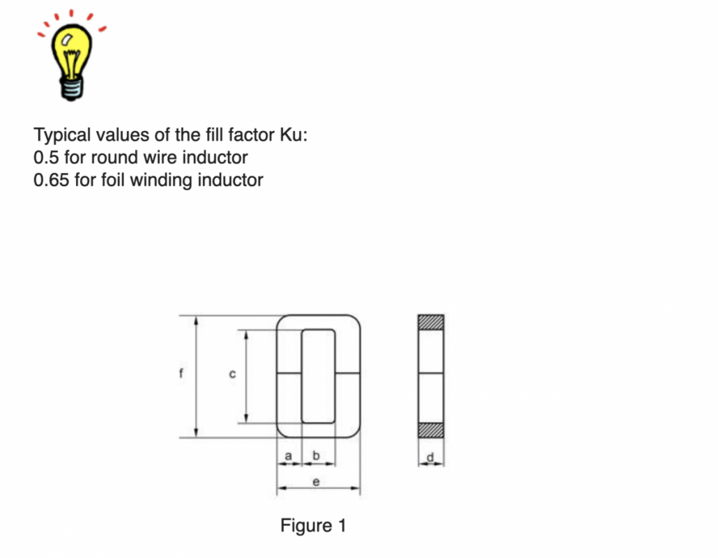
Ku is the core window utilization fill factor
B peak is the flux density in Tesla
f is the operating frequency in Hz
J is the current density in Amp / cm2
The Ap product of a C-type cut core is the product of the available window area (Wa) of the core in square centimeters (cm2), multiplied by the effective cross-sectional area (Ac) in square centimeters (cm2), which may be stated as:
A p = W a x Ac [cm4]
Figure 1 (shown above) shows the outline form of a C-core type inductor; typical of those shown in the catalogs of suppliers.
From this, it can be seen that [Wa] is the BC product, and [Ac] is the AD product.
The AC inductor must support the applied voltage V ind. The number of turns is calculated from Faraday’s Law, shown below:
N=[Vind*10^4] / [L*Kf*Bpeak*f*Ac] [Turns]
Now, we can calculate the air gap with the equation below:
Lg=[0.4*π*N^2*Ac*10^-8]/ L
Where:
L is the inductance, measured in Henry
AC is measured in cm2
Lg is the gap in cm
Keep in mind, the fringing flux will decrease the total reluctance of the magnetic path, therefore increasing the inductance, by a factor F; all of which can be found in the formula below:
F=[1+(Lg/sqrtAc) *(Ln(2*C/Lg))]
Now that our major inductor parameters have been identified, we need to determine the inductor wire size.
Calculate inductor bare wire area Awire: Awire= Ipeak/J[cm2]
Select the wire from the wire manufacturer table. For reference, you can use the table supplied in this link.
Now, we have determined the wire size. If we also know the mean turn length, as well as the number of turns, then we can determine the total length of the wire. From there, we can calculate the DC winding resistance, using the formula:
Rdc= MLT*N*resistance per unit length [Ohm]
Where:
Resistance per unit length as read from the wire tables for the selected wire size.
The losses in an ac inductor are made up of three components:
Copper loss, Pcu 2. Iron loss, Pfe 3. Gap loss, Pg
Copper Losses, Pcu
Pcu = (IL)^2 *Rdc [Watts]
Iron losses, Pfe
For amorphous metal, use the following equation:
Watt/Kilogram=6.5 * f(KHz)^1.51*Bac(T)^1.74
For Nano-crystalline use the following equation:
Watt/Kilogram=1.8 * f(KHz)^1.53*Bac(T)^1.52
Where:
Bac is the flux density, and can be calculated using the formula below:
Bac =[ L*di] / [2*N*A][Tesla]
Variables:
L inductance in Henry Ac core cross section area in m²
Gap loss, Pg
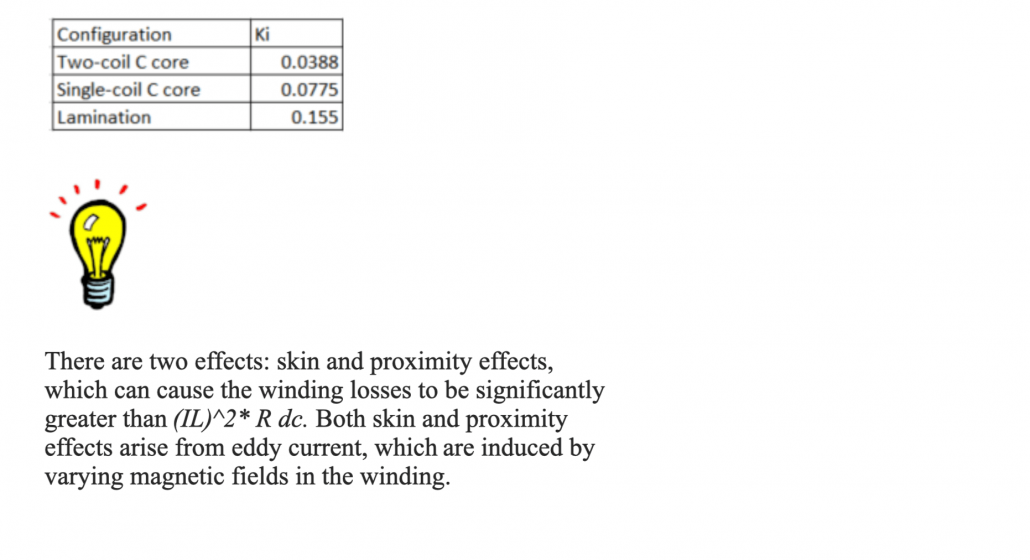
Pg=Ki* a*Lg*f*Bac^2[watt]
Where:
a is the core strip width in cm (see Figure 1 above)
f is frequency in Hertz
Lg is the gap width in cm
Ki is the Gap loss Coefficient
To calculate total indicator losses, use the following equation:
Ptotal = Pcu+Pfe+Pg [Watts]
From here, you can calculate the inductor temperature rise, after calculating the inductor surface area.
As the resistivity of the copper winding increases with temperature, the winding loss increases with temperature as well. In the magnetic materials, the core loss increases with the increasing temperature, above approximately 100-degrees C. The value of the saturation flux density becomes smaller with increases in the temperature. Winding and core loss causes the temperature increase; therefore, the loss must be kept below some maximum value. In practice, the maximum temperature is usually limited to 100-125 degrees C by several considerations, which include the reliability of the insulation on the copper winding, and inductor insulation system.
For Additional assistance in inductor designs, contact DRF Engineering Services with your custom inductor design request.
Who We Are:
We are an innovative design and development team, specializing in power electronic circuitry and power conversion products. We primarily provide product design/electrical engineering services, and have worked with cutting edge companies like yours in the past.
Our services include, but are not limited to the following:
Analog/Digital/Power circuit design
Linear/Switching regulator design
Electro-mechanical product design and program management
Power Management
Manufacturing support
Pre-compliance review and test support (certification and test management for IEC and UL)
Due Diligence and Private Equity Advisory Services
CAD design services, schematics capture, and board layout
https://drfengineeringservices.com/wp-content/uploads/2021/09/blog-1-image.jpg562490Saad/wp-content/uploads/2021/09/logo-1.pngSaad2021-09-03 10:08:092021-09-29 10:49:42Design Guide To Creating Your Next Inductor